Three Phase Brushless Direct Current Motor Control SystemAuthor: Garo MardirossianAuthor information:
Abstract: The current paper presents a system for control of brushless direct current electric motors. This novel system increases the efficiency of the propulsion system of unmanned aerial vehicles and other devices to where it is applied and also lowers the generated by the vehicle or device acoustic and electromagnetic noise. This effect is achieved by properly and momentarily commutating the battery cells comprising the battery block of the vehicle or device. The application of the invention is in robots, unmanned aerial, maritime or land vehicles, electrically driven mechanical devices, etc.
IntroductionThe fast growth of unmanned aerial vehicles research and development in the past few years warrants a revision of the whole avionics and to all of its modules and sub-systems. Special attention is drawn to drone flight duration and range. Smaller sized vehicles less than 50 kg most often utilize electric propulsion driven on batteries. Nevertheless, the number of larger drones based on electric propulsion is growing. A need for battery system efficiency improvement and enhancement of the whole electric propulsion system is of high demand. The current paper is presenting a novel system that improves the efficiency of the electrical propulsion system of drones by commutating the battery cells that power up the aerial vehicles. This novel idea was first published in a patent application and utility model application in 2014. As per the moment of writing this article, there is an approved utility model at the Bulgarian Patent Office for the invention. Area of applicationThe application of the novel idea is in unmanned aerial vehicles, propelled by electricity through brushless direct current motors and powered by batteries. Other candidates for application of the invention may be robots, battery electric vehicles, water vessels, etc. Essence of the inventionAs previously stated, the invention is about a system for battery commutation and control of the electric brushless motors that propel the aircraft. It is exactly brushless motors that this idea is about, because these type of motors are most often used in modern drones. The choice is on brushless motors due to their higher reliability compared to brushed motors. The implemented brushless motors in most present day drones are the so called brushless direct current (BLDC) motors, because they are primarily powered by DC batteries (for example Lithium-Ion or Lithium-Polymer chemistries). The transformation of the DC current to AC, which is needed for this motors to make them rotate is carried out by a controller circuit. This controller regulates also the amplitude of the applied AC voltage and thus defines the rotation per minute of the motor. Laboratory tests have shown that the BLDC motor controllers have higher efficiency when the required motor voltage is close to the battery supply voltage. It is due to the nature of voltage regulation, which is achieved through pulse width modulation (PWM) control. The pulses cause eddy currents in the motor armature and skin effect losses in the motor windings. Minimizing the PWM duty cycle diminishes these negative phenomena and increases the whole system's efficiency by up to 20%. The way of making the battery voltage closer to the required BLDC control voltage is achieved by commutating the battery cells in an appropriate manner. Further benefits form the invention is the lowersed acoustic noise created by the PWM control of the motor controller and released in the air by the vibrations of the motor armature and windings. Yet another benefit from the novel idea is the lowered electromagnetic spurious emissions from the motor windings and wires by the switching transient voltage spikes accompaning the PWM method of voltage control. The block schematic of the invention is presented on the following figure.
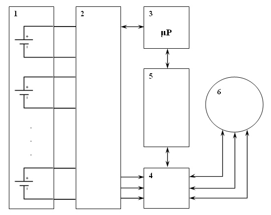
Fig.1. The block schematic of the invention. See text for description.
In the above figure the novel motor and battery control system is disclosed in its major building blocks. Block 1 represents the battery cells. Block 2 is the battery commutation block. It is charged with the task to commutate the battery cells in such a manner so to establish a voltage that is closest and higher to the needed voltage for motor manipulation. This commutation process follows the momentary requirement of the motor controller 5 and has to be fast. Block 3 is the microprocessor that is appointed for management of all control tasks. The microprocessor sends commands to the battery commutation block 2 and to the motor controller block 5. Block 4 is the motor control transistors block. It consists of six transistors configured in push-pull transistor pairs. Block 4 is standard block and hence is not shown in this article. Finally, block 6 is the BLDC motor. Benefits of the presented inventionAs already mentioned the benefits are higher efficiency of the electric propulsion system as a whole and lower acoustic and electromagnetic noise. An description of a sample system, utilizing the inventionThe brushless direct current motor is controlled by two mutually related methods. The first method is the commutation of the motor windings. Most BLDC motors are three phase synchronous motors and permanent magnets in the rotor and armature and windings int he stator. There is no electrical connection between the rotor and the stator, only magnetic coupling. In order to rotate the motor windings should be switched on and off in the right moments of time. This switching, called commutation, appeares due to a feedback that signals the motor controller when it should switch the voltage to the individual motor windings. The second method of BLDC motor control is the voltage applied to its windings. The counter-electromotive force (CEMF) also called back electromotive force (BEMF) generates back electromagnetic voltage that is dependand of the rotations per minute (RPM) of the motor rotor. The faster the rotor revolves, the higher the BEMF voltage is. The are in linear relation. On the other hand, by applying higher voltage tot eh motor windings that the curently generated BEMF voltage, a current will start to flow in the motor windings and power shall be injected in the motor. This power wil tend to increase the motor rotations per minute until the BEMF voltage equls the applied by the controll er voltage to the motor windings. In order fot hte controller to achieve certain rotation per minute, an exacrt volrtage has to be applied to the motor windigfs. As the battery has constant voltage output, the reuqired voltage is achieved thorugh pulse width modulation as mentioned earlier. THis PWM voltage is filtered out buthe inductance of the motor windings that act as inductors and have high positive reactance against frequenceiin the range ot 8 to 30 kHz. But these inductors are not perfect. These inductors consist not only of the motor windings but of the motor armature. Is in electric transformers, the motor armature is made up of thin laminations in order to incereate the efficienscy at higher frequencies, but when frequencies in the described range of 8 to 30 kHz are used even these laminations are not enought to couteract the induces eddy curretns in the armature. As a result, power is lost and heat is dissipated in the motor armature. Further loss of power is observed in the motor windings that are made up ot copper, aluminum or silver wires. Power loss due to skin effect and proximity effect is inevitable, and the higher the PWM frequencyis applied, the higher the loss is in the motor windings. Lowering the PWM frequency is not an option because low frequencies will result in current spikes (low level of filtration) and iwll increase the effective current in the motor windings thus increasing active power losess in the active motor winding resistance. Also low PWM frequency tends to be audible, which is unundesired effect in most application. For the above reasons, frequences above 16 kHz are commonly applied. The novel system of battery comutaiton and motor control involved comutating the battires at any given moment in order to achieve voltage before the motor controller that is closest possibelt o the needed voltage. The rest of the voltage control is perforemd by the PWM. Of course the battery voltage should always be higer the needed motor control voltage. ConclusionNovel systems for electrically propelled aerial vehicles promise an increase in efficiently and effectiveness of the vehicles where they are applied to. Work in this sphere has been taking place at Space Research and Technology Institute at the Bulgarian Academy of Sciences since 2014 and is still ongoing. Further inventions by the same team of inventors in the field of unmanned aerial vehicles address UAV airframes, aircraft design, multirotor helicopter models, airplanes with vertical takeoff and landing capabilities, etc. References:
|
 garo.mardirossian
 gmail.com