Bistable Relay Computer 44 (BRC44)Author: Svetoslav ZabunovAuthor information:
Abstract: Bistable Relay Computer (BRC) family of relay based educational computers was created by Svetoslav Zabunov in 2015 as an educational project to teach students and pupils alike of the inner workings of the computer and as well to present the history of computers to all people who might be interested in this irresistible and passionate realm of wonders.
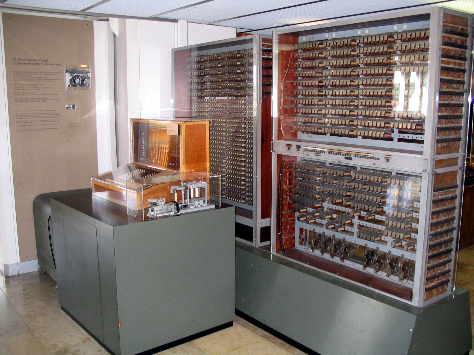
BRC 44 is the first computer of the BRC series and most probably the only one, that will leave the theoretical drawing board and become a real prototype working at Sofia University, Faculty of Physics. It is in process of development with complete schematic diagrams, instruction set and architecture and at the moment of writing this article the computer's hardware is 50% complete, so stay tuned, it shall be soon ready and clicking! IntroductionRelay computers were the first programmable digital computers. The world's first working programmable and automatic digital computer was the relay computer Z3, designed by Konrad Zuse (see fig. 1). The Z3 computer contained 2000 electromechanical relays. It used a 22-bit floating point words presented with binary system and operated at speed of 5 to 10 clocks per second. The program code and data were stored on punched film.
Fig.1. Replica of the Zuse Z3 computer in the Deutsches Museum in Munich, Germany. Photo
 by Venusianer / CC BY-SA 3.0. by Venusianer / CC BY-SA 3.0.The Z3 computer first started work in Berlin in 1941 at the German Aircraft Research Institute, where it was used to perform statistical analyses of wing flutter. The next relay computer of Konrad Zuse was Z4. It was completed a short time before the end of World War II. The bases for relay computers were introduced independently of Zuse in 1937 by Claude Shannon who theorized on mapping Boolean algebra onto electronic relays. In the United States a relay computer was also built. It is eventually known as Harvard Mark I, but was initially called the IBM Automatic Sequence Controlled Calculator (ASCC). It was later called Mark I by Harvard University’s staff. In contrast to Z3, beyond electromechanical relays it involved mechanical systems such as rotating shafts and clutches. One of the first programs ran on the Harvard Mark I was initiated on 29.03.1944 by John von Neumann and solved problems met in the Manhattan project. Bistable Relay Computer 44 (BRC44)Bistable Relay Computer 44 (BRC44) is a 4-bit computer with 4-bit ROM data bus. It implements Harvard architecture. BRC44 is a modern computer aimed at education of computer technologies in universities and schools and dissemination of computer knowledge among all people around the world. The computer was conceived in 2015 as part of the Bistable Relay Computer series (BRC series), designed at Zabunov Laboratories. Currently it is the only bistable relay computer of the BRC series that has a prototype under construction. BRC44 is built entirely out of bistable relays also known as latching relays and does not use any monostable classic type relays, any transistors, any integrated circuits, any electronic vacuum tubes or any semiconductors except diodes. In fact the building components of BRC44 are:
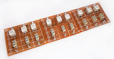
Fig.2. A part of the BRC44 sequencer module
As mentioned earlier, BRC44 implements Harvard architecture. It has 8-bit address space for the program ROM and 4-bit address space for RAM registers. The program ROM is realized using DIP 8-position switches. Every switch stores 8 bits of program data. The ROM data bus is 4-bits wide and multiplied by ROM address space of 256 gives 4 * 256 = 1024 bits of ROM memory. ROM is made as a rectangular matrix of 16 columns addressed by the most significant 4 bits of the address byte and 16 rows addressed by the least significant 4 bits of the address byte. There are 128 8-position DIP switches comprising the ROM. RAM occupies 16 4-bit RAM registers consisting of bistable relays, one relay per bit and 64 relays for the whole RAM memory. There are two working registers AX and BX and two flags CF (carry flag) and JF (jump flag). The current values of the working registers AX and BX, the flags and the first two RAM registers are displayed using 13-segment digital display showing the value of each register as hexadecimal digit (from 0 to F). Instruction opcode is also 4-bit wide, i.e. there are 16 standard instructions, most of which have no parameters, except 2 of them:
There is one compound instruction for calling subroutines CALL a, which is encoded as a sequence of three standard instructions:
Thus all instructions are really 17, not 16. The full instruction set of BRC44 is shown in the following table:
Table 1. BRC44 instruction set
The processor uses a sequencer (a finite automaton) with 8 states. There are 9 states in the current design, but the last state shall be, at least for now, left unused. The following figure shows the BRC44 simulator. Fig.3. BRC44 simulator
ConclusionAt the moment of writing this article the BRC44 prototype is 50% ready and is expected to be complete in early 2017 and start clicking by then. |
 SvetoslavZabunov
 gmail.com