Circularly Polarized 2.4 GHz Antenna Suitable for Small UAVsAuthors: Georgi Sotirov and Svetoslav ZabunovAuthors information:
Abstract: The current paper describes a novel circularly polarized antenna meant to be employed on board of small unmanned aerial vehicles (UAVs). The antenna has the advantage of having a nearly isotropic radiation pattern as well as exhibiting a simple structure that is easy to manufacture and maintain. Further, the proposed design is lightweight and has inherent low air drag, which is beneficial when used on very small drones or fast flying aircraft.
A simulation of the proposed antenna has been carried out using 4NEC2 free simulation antenna software. Through these means, the radiation pattern, gain, bandwidth and other parameters of the antenna were calculated.
Keywords: Circularly polarized antenna design, Unmanned aerial vehicle antenna IntroductionThe authors were drawn to the idea of developing a novel antenna design for small unmanned aerial vehicles (UAVs) due to the need for experimental work on drone designs, instrumentation testing and autopilot innovations. The target radio band is 2.4 GHz, a common frequency band used extensively in the drone arena for control of the UAV as well as for telemetry and video signal transmission. Circular polarization has a number of benefits, most significant of which is the odd reflections attenuation (Gao et al., 2014). The base station may use two circularly polarized antennas with opposite polarizations in order to capture not only the direct wave, but also the first reflection. These two antennas would work in a diversity scheme. Another benefit of employing circularly polarized antennas with UAVs is the lesser dependence of the signal distortion on aircraft attitude. Although 2.4 GHz yields a small wavelength and hence small antennas in size, when applied to small drones the antenna still has significant dimensions and may hardly be incorporated inside the fuselage. Our objective was to develop an antenna for testing and experimental purposes that is:
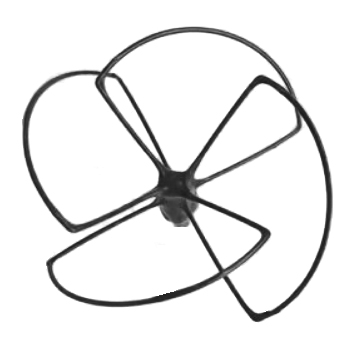
Certain existing models do satisfy some of these prerequisites but not all – for further information see the next section. State of the artWhen it comes to circularly polarized antennas for drones one of the first choices is the Skew-Planar wheel antenna (Fig. 1). The Skew-Planar Wheel antenna was presented for the first time in the QST magazine in November 1963 (Mellen and Milner, 1963). It was further described in the ARRL Antenna Book from 1964. The antenna has four identical elements, resembling plant leaves. The elements are curved and hence are hard to manufacture. The Skew-Planar Wheel antenna is based on the Cloverleaf antenna invented by Phillip H. Smith (Smith, 1947). That’s why the variations of the Skew-Planar Wheel antenna are colloquially called Cloverleaf antennas. These variations differ from one another mainly in the number of elements and the most wide spread one of those is the three-leaved Cloverleaf antenna (Prakoso et al., 2017).
Figure 1. Skew-Planar Wheel antenna
Another prominent circularly polarized antenna is the turnstile antenna. It was patented in 1937 by George H. Brown (Brown, 1937). This design is clearly unsuitable for small drones as its construction rigidity is inferior to the cloverleaf antenna family (Fig. 2).
Figure 2. Turnstile Satellite Antenna – 137MHz close-up. Original work: K. Krallis, SV1XV, via Wikimedia Commons
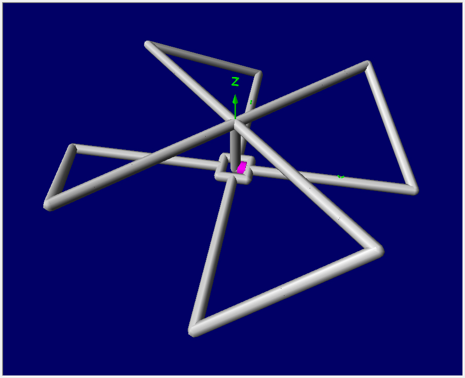
There are a number of other circularly polarized antenna designs (Yang et al., 2014; Kan and Waterhouse, 2001; Kim et al., 2007; Huang, 2001) but being based on printed circuit board technology are unsuitable for the applications in drones due to their significant weight and pronounced aerodynamic drag. ConstructionThe current design borrows the idea from the Skew-Planar Wheel antenna, but alters the construction of the antenna elements to encompass only straight wire segments instead of curved ones. The unbent wire segments are easier to manufacture and maintain. This compromise is appropriate for short wavelengths that are inherent to the 2.4 GHz band and above where the added weight is insignificant. A general view of the antenna design can be observed in Fig 3.
Figure 3. General 3D view of the antenna structure
The antenna dimensions may be examined in Fig. 4. It is an interactive figure where the reader may calculate the antenna elements dimensions according to the chosen centre frequency. Figure 4. A calculator for the antenna elements dimensions as a function of centre frequency
Antenna simulationThe proposed antenna design was simulated using the free 4NEC2 software. In Fig. 5 authors are displaying an interactive figure that can be used to generate a NEC file for feeding the 4NEC2 software. The figure requires the reader to input certain antenna parameters in order to generate the NEC file. Figure 5. NEC file generator
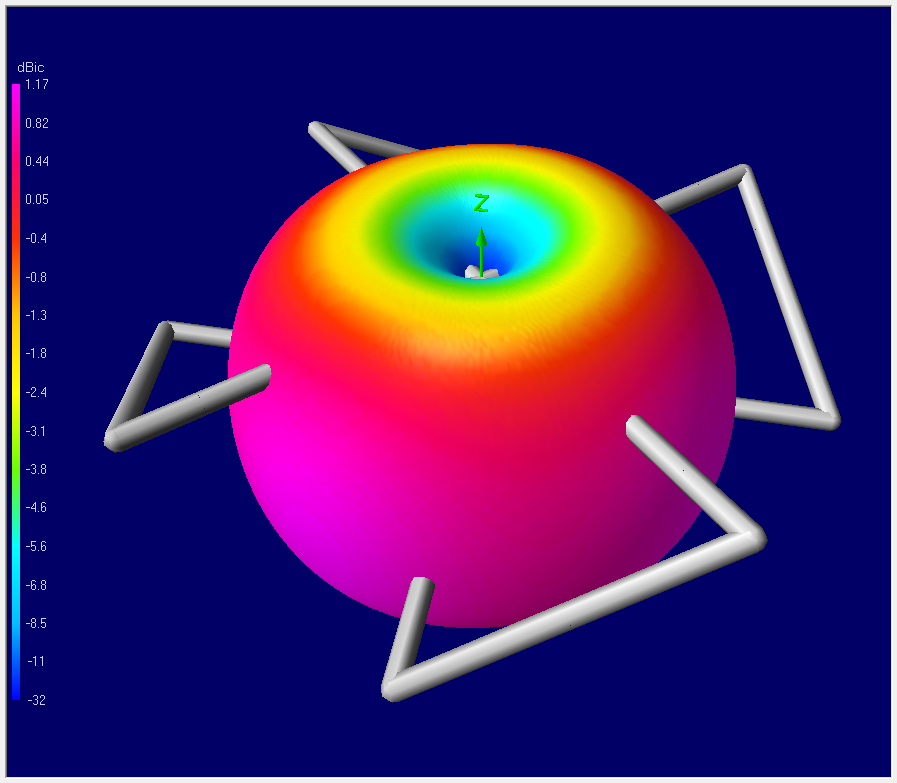
For this simulation a centre frequency of 2440 MHz was chosen. After performing the simulation we observed the following radiation pattern exhibited from the Total Gain 3D visualization (Fig. 6).
Figure 6. Total Gain 3D visualization
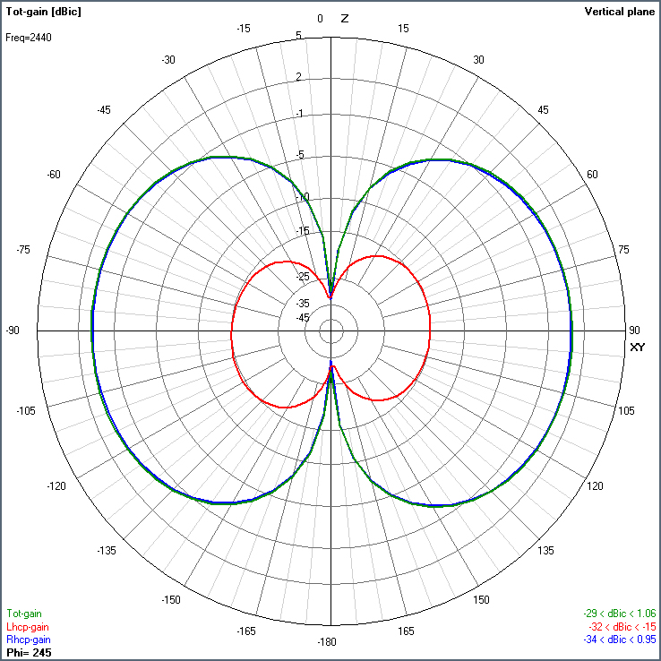
Because the antenna radiation pattern is axially symmetric, an equally informative figure of the gain may be produced using a 2D chart in the vertical plane shown in Fig. 7. Here the right-handed and left-handed circular polarization gains are depicted using blue and red curves respectively. The antenna is right-handedly polarized and the left-handed polarization is a parasitic one.
Figure 7. Total Gain in the vertical plane (2D visualization)
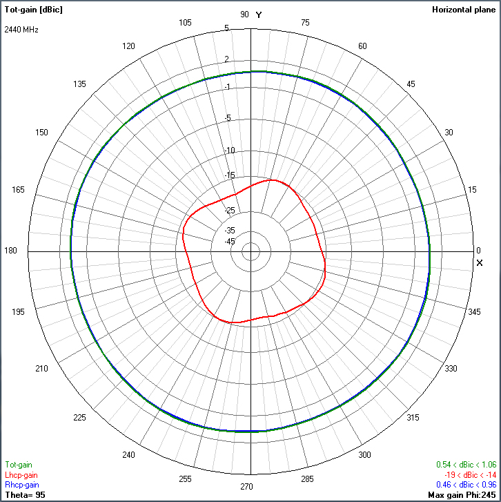
Antenna gain has dips along the vertical axis, which destroy its perfect omnidirectional radiation pattern, but these dips are narrow and by mounting the antenna vertical axis to be coincident with the vertical axis of the fuselage of the aircraft, the dips will affect the overall antenna performance marginally. The same 2D plane chart of the antenna gain, but this time in the horizontal plain, is shown in Fig. 8.
Figure 8. Total Gain in the horizontal plane (2D visualization)
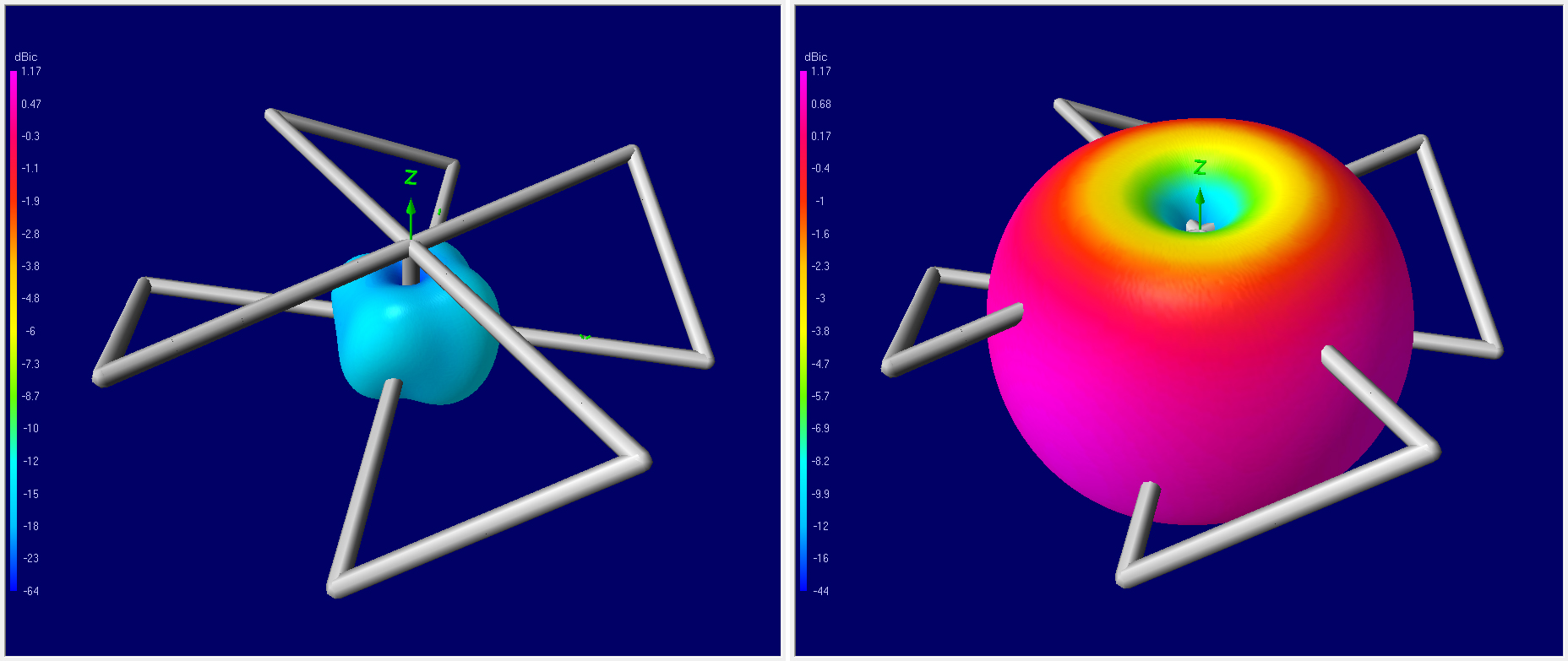
Here one could identify clearly the difference between the right-handed circular polarization gain and the left-handed one. Fig. 9 reveals the same information but in 3D view.
Figure 9. Left-handed circular polarization pattern (left) and right-handed circular polarization pattern (right)
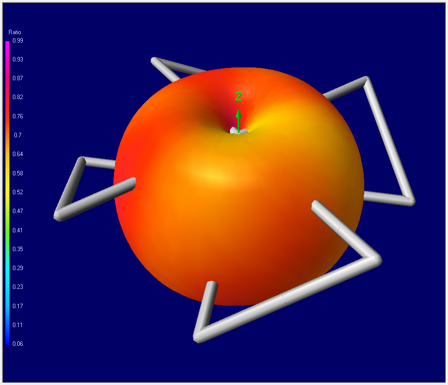
Another parameter describing the quality of the antenna is its axial ratio of the circular polarization (Fig. 10). It is defined as the ratio between the minor and major axis of the polarization ellipse. If the ellipse has equal minor and major axes it transforms into a circle, and the antenna would be perfectly circularly polarized – the axial ratio would be equal to unity (0 dB).
Figure 10. Axial ratio of the circular polarization
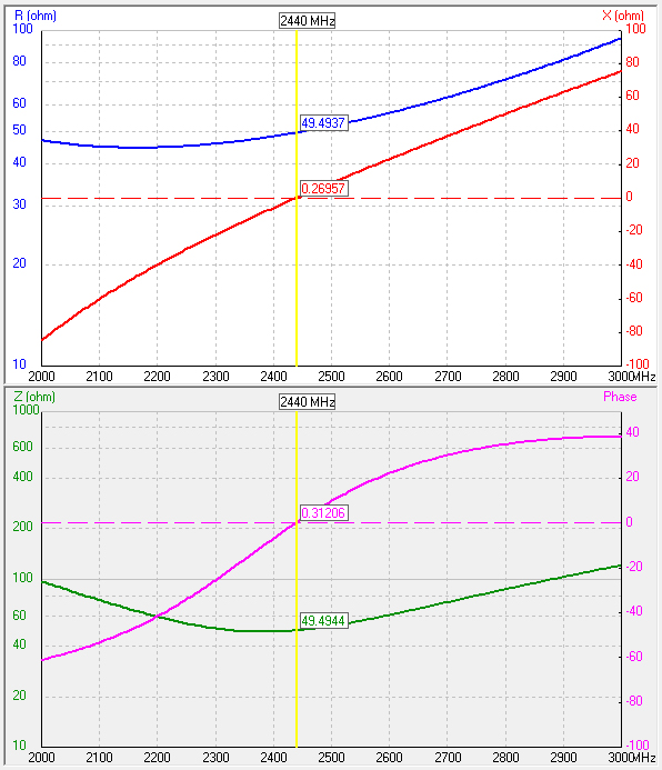
When it comes to impedance, the antenna was designed to be fed with a 50 ohm feed line. (Fig. 11). The antenna impedance versus frequency was calculated as an active and a reactive component (Fig. 11 above). Also, the impedance as modulus and phase was shown in Fig. 11 below. A good match of 49.49 Ohms is observed at the centre frequency. The reactive component is below 0.3 Ohms or put another way, the phase at the centre frequency is below 0.32 degrees.
Figure 11. Antenna impedance versus frequency. Impedance was calculated in active and reactive components (above). Yet, the total impedance as modulus and phase is shown (below).
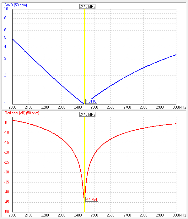
The same data, but interpreted as the feedline matching behaviour is demonstrated in Fig. 12 where the standing wave ratio (SWR) and the reflection coefficient are depicted. The SWR is extremely good being only 1.01. Considering an acceptable SWR of 2.0 yields antenna bandwidth from 2250 MHz to 2700 MHz, totally overlapping the bands of interest.
Figure 12. Antenna standing wave ratio and reflection coefficient
For example, the Wi-Fi IEEE 802.11 standard uses the frequency band 2400 – 2495 MHz. The analogue frequency modulation video systems on 2.4 GHz occupy the frequency range 2370 – 2510 MHz. For both applications the antenna offers maximum SWR below 1.5, which translates to only 4% power loss. ConclusionsThe proposed design satisfied the prerequisites establish in the Introduction section of this material, namely it is: easy to manufacture and maintain; guarantees close to omnidirectional radiation pattern with the major exception in the vicinity of the two dips along the vertical axis; the antenna is lightweight, and may be constructed of duraluminium wires; the device has low air drag, due to its wire-based construction. Antenna design of circularly polarized RF transmission and reception antennas is gaining attention in the drone community for the described above advantages. This motivates the authors to continue their work in the field aimed at developing new circularly polarized antenna designs References:
|
 gsotirov
 space.bas.bg